Thursday, June 28, 2012

Panoramic Mirror


More mirrors!!! Awesomeness!!  This time we are back to mimic panoramic imaging. Panoramic imaging covers up to 360 degrees, this is while the approximated field of view of humans is 95 degrees out, 75 down, 60 in and 60 up!

As shown in the picture below, the  panoramic mirror is  surrounded by walls so far away from the optical axis of the mirror  that the walls seem like a cylinder.  This mirror reflects the image of an object positioned on the wall .  In all the previous cases that we studies, the object was positioned on the floor. However, regardless of the position of the object, out goal remains the same.  We want to find the equation of such mirror with orthographic projection.


As shown in the picture, we draw the tangent line to the mirror where the light ray hits the mirror,  By forming a triangle we show that
We know that tangent of an angle is opposite over adjacent.  Thus, we find the tangent of angle 2 theta as following:


Now, we can easily use double-angle identity,


By equating the two equations, we have a differential equation to solve in Maple based on x and a:

a is a scaling factor and the bigger the a, the bigger the field of view and less distortion.  
1) a=1
2) a=500
3) a=1000
However, we tried to further reduce the distortion in the mirror by increasing a beyond 100, but we didn't notice any significant change in the distortion pass that point.  

Monday, June 25, 2012

Minimum Distortion

As we experienced with spherical and parabloid mirrors, when the mirror is of a quadratic function, there is a great distortion in the image.  In a study done by Andrew Hicks, University of Pennsylvania, it was found that when the distance between the object and the image plane is of a linear function, the image captured by a mirror in both perspective and orthographic projections has no distortion. 

In the picture below, you're looking at an orthographic projection.  From the Law of Reflection, we know, the angle of incidence = the angle of reflection = ϴ. From the paper we were given the
tan(ϴ )=F'(x) and we used the image plane, tangent line from the point on the mirror, and the parallel light ray to uderstand where the equation came from.  In the picture, the angle between the normal line and tangent line is 90 degrees.  To get the smaller angle for our traingle and solve for the unknown angle formed by the interesection of the image plane and tangent line, we identified the angle as (90-ϴ ).  The angle formed from the interesection of the parallel line an the image plane was know to be 90 degrees.  With this information from the picture, we go that ϴ was equal to our unknown angle, and the tan(ϴ) was equal to F'(x) because it represented the raise and run from the image plance to the point on the mirror containing F(x). Our was as follows


ORTHOGRAPHIC PROJECTION GRAPH


 With the infromation from the picture, we used the double angle identity for  the tan function to get
We were then able to use Maple to put in the function and get  an equation for F'(x).  In the new form of an ordinary differentiable equation, we solve for F(x) using it's derivative F'(x).  The equation for F(x) was the surface of our mirror with minimal distortion and we then graphed it in Maple to get a visual idea of what our discovered mirror surface looked like.  THE END

FUNCTION OF A MIRROR SURFACE IN ORTHOGRAPHIC PROJECTION 

`

Friday, June 15, 2012

Spherical Mirror Example

Spherical Mirror   

Earlier we had an example of how to find the coordinates of an object that reflected off an paraboloid mirror. Today we found the coordinates of object that reflected off a spherical mirror from an orthographic camera.
We used a sphere that was centered at coordinates (0,1) and had a radius of 1. The image plane is located at  (X0,k) where k could be any y-coordinate since our orthographic perspective won't affect our results.  
OUR WORK AND PICTURE


Thursday, June 14, 2012

Spherical and Paraboloid Mirrors!


The big concept introduce in high school Physics is the Law of Reflection. So here is a little a bit of a refresher. This Law states for a mirror , angle of incidence and the angle of reflection are equal. Let's make use of this law.
Task 0: create the following Povray scenes
A. Create a spherical mirror with perspective and orthographic projection

Perspective

Orthographic


B. Create a praboloid mirror with perspective and orthographic projection.
    

    Perspective

Orthographic

Doesn't it look Fun? The more you learn, the more fun it gets! It's our promise to you!
Paraboloid is a quadratic surface with a conic section. It could be in the form of elliptic or hyperbolic parabola. Except for parabola the other two have 2 foci. When the light ray passes through one of the focus points then the reflection always passes through the other focus points.
  • A parabola has an equation : y = ax² +bx+c
  • An Ellipse has an equation:  (x²/a² )+ (y²/b²) = 1
  • A Hyperbola has an equation: (x²/a² ) - (y²/b²) = 1
Task 1:
Find the coordinates of the object point P, by backtracking the path of light.

What we know:
  • parabolic mirror with focus at (0,1) and that passes from the origin
  • perspective camera with a pinhole at (0,-1); image plane at y = -2.
Here is a picture for you guys to follow along with us.


Our goal it to find the coordinates of point P. 
  1. We will find the slope of the line with coordinates (x, -2) and (0,-1).
  2. Use the coordinates of the focus point  to find the equation of the parabola.
  3. Find where the parabola and line intersect to determine the other point in line 2 to write an equation of the lind containing point P.
  4. Use the equation of the line contain point P to find its coordinates and the location of the light source
  5. Good job! We have worked backwards and located a factor in the process of combining cameras with mirrors.


Wednesday, June 13, 2012

Povray for Dummies

Let's play a game.  How do you feel about Povray?  It's really fun.  Here are the rules for the game:
1.get creative!! explore the help icon!! Read about the"cool" features available to play with it.
2.  never forget to include  #include "colors.inc"  and  #include "shapes.inc" at the very beginning of your file!
3. make sure, you're comfortable with the x, y and z coordinates.
4. apply the right lighting, otherwise all you see is infinite darkness!!
5. don't forget about your camera projections: perspective, orthographic, cylinder and fish eye!!
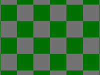
6. Checkers!! remember the rgb percentages!!! r: red, g: green and b:blue
7.enjoy!

Task # 0:
Create a plane of checkers:
  • Fish eye
  • Orthographic
  • Perspective


Task #1:
Remember your drawings when you were 5? That's what we're looking for.  Create a house and a tree.


Task #2:
 3 balls of the same size sitting in a row. The balls should be covered w/checkers.
  • Perspective
  • Orthographic


Tuesday, June 12, 2012

Camera Models

What is required to form an image?

  • projection model
  • physical realization of a model


We discussed two projection models: perspective and orthographic projections


Perspective Projection:

  • how you view the world
  • can be demonstrated with a pinhole camera
  • has relative distances of objects
  • wide field of view
  • short focal length (distance between pinhole and image)


Orthographic Projections:

  • the pinhole is at "infinity"
  • no perception of distance and objects appear side by side
  • narrow field of view
  • light travels in parallel lines
  • long focal length


Map Making Projections


Look at the map on the left, Africa is roughly the same size as North America.  But, the reality is very different that what is shown in this map.  As demonstrated in the map in the right, many countries, including the United States could fit into Africa.  This is the result of distortion in mapping.  
Our earth is in the shape of a sphere with a positive curvature.  Any shape with a curvature greater than zero  cannot be flatten or modeled by a piece of paper. Given the spherical shape of earth, the transformation of every point from the sphere (3D) to a 2D map can not preserve the  area, angle, and distance together and some properties must be sacrificed in the projection.  There are various types of projections, each of which preserve different properties, such as: cone and cylinder projections.


The conical projection is area preserving.

The cylindrical projection is not area preserving.  In fact, it's angular preserving or conformal.

How Digital Images are Created

Have you ever wondered how:
  • digital images are created?  The digital images are rectangular arrays of pixels. Each pixel is represented in regular charge coupled device (CCD) chip by recording the brightness value. 
  • black and white images are created? A black and white image, mathematically, is a single matrix of numbers from 0 to 255. 

  • color images are created? Color images are represented by three matrices of RGB (red, green and blue).

The Intro to Imaging with Catadioptric Sensors

So many people in the past have attempted to capture a wide angle image without any distortion to the viewer. Have you guys ever heard of Robocup? It's World Cup for robotic dogs with cameras and sensors attached to them in order to determine their movements.
 
The objective of the game is the same as soccer, to put the ball in the opponent's net.  Sounds simple enough.  BUT, the problem was the long time required for the dogs to scan the field because of the limited angle of view from the camera.  This problem was detrimental to the fast pace of the exciting game of soccer.  The cameras designed to address   the problem were too heavy for the dogs to function properly and were too expensive.  Nonetheless, researchers in their later studies made use of mirrors in combination with cameras to obtain a wider view.  That's where we come into the picture.  The Mirror Squad's mission is to find a solution for capturing a 180 degree field of view (FOV) with minimum distortion. 

Are you guys up for a little bit of history? We promise to make fun! Before all of us were born, around 400BC, Aristotle was among the first to comment on how sunlight beam going through a square hole in a dark room create a circular image. This phenomenon was later used to created the Camera Obscura or more popularly referred to as Pinhole Camera.  When light passes through a pinhole camera, it turns the image up-side-down because light travels in a straight line.


 Due to the up-side-down image created in above process, later a mirror was used to reflect the image right-side-up.

heyyyyyyy!

Shalise, Ozias, Mahalia, Abu and last but not least Emek aka. The Mirror Squad!!!
This is our first post! WOOOOOOHOOOOO!!! Now, we have a good reason to stand in front of the mirror forever and ever and ever!!!
But, it's time to get serious!! Let's keep it old school and talk about different solutions to wide angle imaging.